
NOTE: custom routing and some of the features described in this article, such as manipulating propagation labels, are not supported if using Virtual WAN Routing Intent, a functionality required for cross-region communication over multiple secured hubs.
Some organizations use Virtual Routing and Forwarding (VRF) tables in their networks to segment traffic at the routing level. Transporting that concept to Azure can be challenging, since virtualizing an Azure network is not easy. If you think about it, your Azure network is already its own VRF in a way, it is a slice of Microsoft’s infrastructure. Would it be possible add a second layer of virtualization, to implement a VRF-like solution in Azure networking?
Azure Virtual WAN is one of the options in Azure to implement your cloud network (see for example this recent post where I describe different design options with Azure Networking). It even offers the possibility of what is called “custom routing”, with which you can achieve this VRF-like functionality for your Azure Virtual Networks (see the Red/Blue VNet scenario in the official docs), but this feature is not extensible to branch connections like ExpressRoute, SDWAN or site-to-site VPNs back to your on-premises data centers.
TL;DR: to do comprehensive network virtualization for both VNets and branches you will need a Virtual WAN hub per VRF. In the following diagram you see a blue, red and green hub, where blue, red and green VNets and branches are respectively connected. Using Azure Virtual WAN custom routing (association and propagation settings) you can selectively configure a VRF to talk (or not) to the others. For example, you could configure the green VNets and branches to act as a sort of “shared services”, so that they can communicate to both red and blue, while red and blue still cannot communicate to each other.
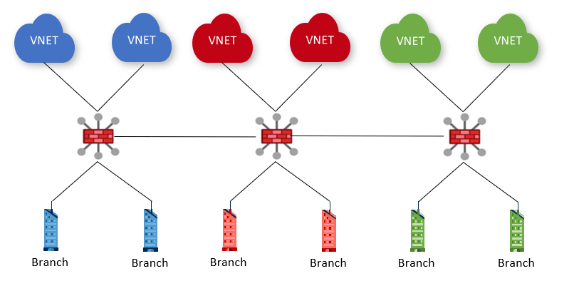
Note that in the diagram above I am using the icon for the “secured hub”, that is, a Virtual WAN hub with an Azure firewall deployed. However, secured hubs in Virtual WAN have some limitations today (most notably, the lack of inter-regional support). Please consider the diagrams in this article always under the light of Virtual WAN current functionality.
Does this make sense?
The first discussion I try to have with customers following this approach is whether this makes sense at all or not. I am frankly not a big fan of segmenting traffic via routing in enterprise networks, since it can get very complex very quickly, and not having logs of dropped traffic can be a big handicap in breach analysis exercises or postmortem investigations. That being said, there are some scenarios where this routing-based segregation can be the best strategy to follow.
An additional consideration are possible dependencies with Virtual WAN routing intent. As long as you dedicate a virtual hub for a given VRF, you shouldn’t need custom route tables or static routes (not supported in routing intent, as documented in that web page), but only to modify the propagation labels of the connections. However, since Virtual WAN routing intent is still in public preview, there might be some changes as it comes to General Availability, and at this point I don’t know whether custom label propagation will be supported there.
Association and Propagation
The most important concepts to understand to achieve our goal are route table association and propagation in Virtual WAN:
- A VNet or a branch (in Virtual WAN “branch” means either S2S/P2S IPsec, ExpressRoute or SDWAN) connection association to a route table will dictate which routes will be propagated to that VNet or branch. A connection must always be associated to some route table, so that Virtual WAN knows which routes to send.
- Optionally, connections can propagate to route tables. If they do, the routes from the connection (the VNet prefixes or the routes advertised from onprem via BGP) will be dumped into the corresponding route tables. A connection can propagate to zero, one or multiple route tables.
- Each connection can explicitly propagate to a single route table (usually in the local hub).
- To facilitate propagation to multiple route tables, label-based propagation is possible too, where a route table will propagate to all the route tables (in the local and remote hubs) that match its tags.

Isolating hubs from each other
If you configure a hub’s connections to only propagate to the local route table(s), the others will not know about its routes. In essence, here the configuration that you would have where all VNet and branches from each hub only propagates to the local default route table (where they happen to be associated too):
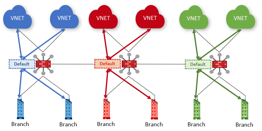
To do this, you need to remove the “default” label from the propagation in each connection, since this is the label responsible for the cross-hub propagation in an out-of-the-box Virtual WAN configuration.
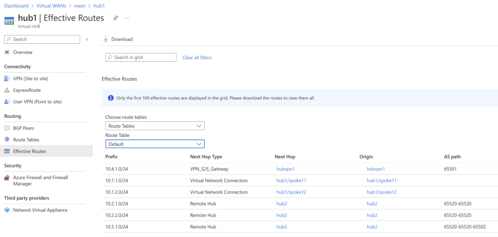
For example, I have here a sample Virtual WAN with two hubs. Hub 1 has connections for the VNets 10.1.1.0/24 and 10.1.2.0/24, and the branch 10.4.1.0/24. Hub 2 has the VNets 10.2.1.0/24 and 10.2.2.0/24 and the branch 10.5.1.0/24. With the default configuration (connections propagating to the “default” label), each hub can see its own routes, and the routes of the other hubs (if you notice the 65520 ASN prepending you can easily identify which routes come from other hubs):
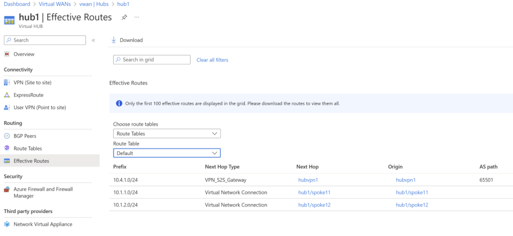
After removing propagation to the “default” label in both VNets and branches on the hubs, you would notice that only the local routes appear in the effective routes of the hub now:
VRF route leaking
Could we implement in this design the “shared services” pattern? That is, achieving that the green VNets can talk to both blue and red, but blue and red still don’t see each other? We would need some custom propagation, so that the green connections do propagate to the default route tables in the blue and red hubs, but the blue/red connections only propagate to the route tables in the green hub. This diagram shows this cross-hub propagation between the blue and green hubs (the same would have to be done for the red and green):

I have expanded my 2-hub setup to 3 hubs, and I have added some WAN connectivity (IPsec, ExpressRoute and SDWAN). I use the label “shared” to propagate to the “Shared services” hub default route table. Here is how the VNets are configured (note the Association and Propagation columns):
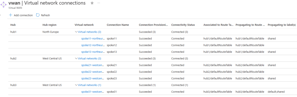
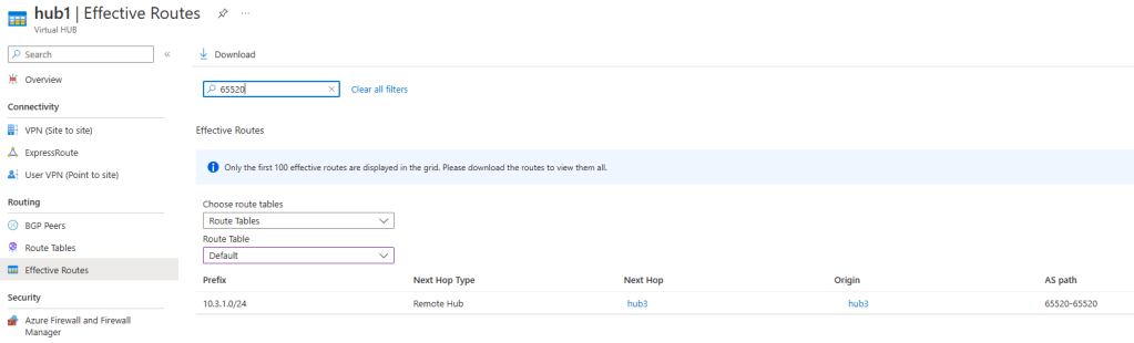
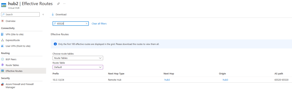
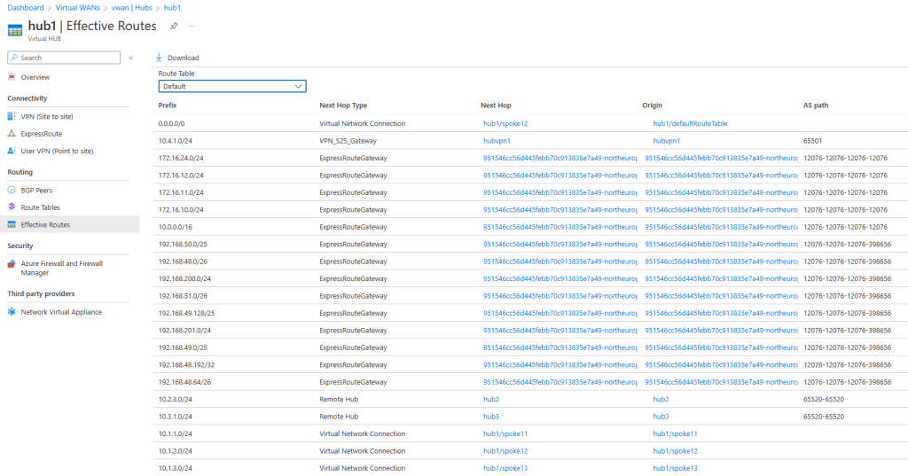
If we have a look at the effective routes of the blue and red hubs learnt from remote hubs (filtering on ASN 65520), you will see that only the shared service VNet 10.3.1.0/24 is learnt (the “shared” hub only has one VNet). The reason is because neither blue nor red VNets propagate to the “default” route table:
If we have a look at the default route table in hub 3 (our “shared services” hub), since we labeled this route table with “shared”, and both hub 1 and 2 VNets are propagating to this label, we will see the VNets and branches (I have in this environment site-to-site, ExpressRoute and SDWAN connections) from both hubs:
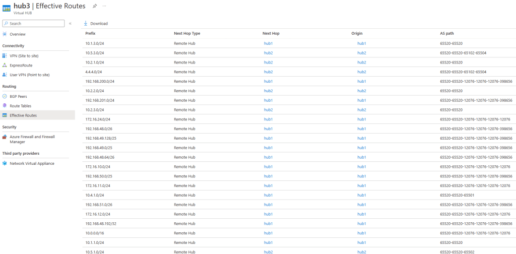
For reference, here the types of routes that appear in the previous screenshot:
- AS path 65520-65520 (such as 10.1.3.0/24): these are VNets directly attached to the other hubs
- AS path 65520-65520-65501 (10.4.1.0/24): this is a site-to-site IPsec connection attached to hub 1
- AS path 65520-65520-65502 (10.5.1.0/24): this is a site-to-site IPsec connection attached to hub 2
- AS path 65520-65520-65102-65504 (4.4.4.0/24): SDWAN prefix connected to an NVA deployed in hub 2
- AS path containing 12076 (such as 172.16.24.0/24): routes coming from ExpressRoute, in this case from an Azure VMware Solution environment via Global Reach
In a nutshell: the propagation customization technique via labels applies both to VNet and branch connections.
Breaking this design
There are two reasons why this design cannot be implemented today in a single hub:
- Virtual WAN connections in the same hub need to have exactly the same association and propagation configuration. This makes it impossible having “blue” and “red” branch connections in the same hub.
- You cannot put a “shared services” VNet in one of the other hubs. There is a subtle reason for this one, and this is what we will explore in this section.
In a new version of the design, I have a default route table configured in each hub, going to an NVA in one of the spokes (spoke12 in hub1, and spoke22 in hub2). This is a very common design with firewalls in Virtual WAN, to send Internet traffic through a North/South perimeter firewall for inspection. For example, in hub2, there is a default route table going to an NVA in spoke22):
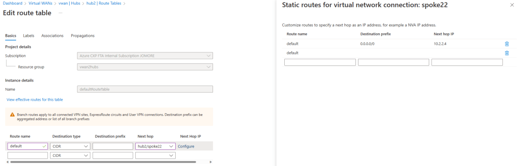
Additionally, we will put a VNet in a custom route table “shared” in both hubs (focus on the associated column):

Let’s see if we can connect to a red VM (10.2.1.4) from one of the blue VMs (10.1.1.4):
jose@spoke11-vm:~$ ip a
1: lo:  mtu 65536 qdisc noqueue state UNKNOWN group default qlen 1000
    link/loopback 00:00:00:00:00:00 brd 00:00:00:00:00:00
    inet 127.0.0.1/8 scope host lo
       valid_lft forever preferred_lft forever
    inet6 ::1/128 scope host
       valid_lft forever preferred_lft forever
2: eth0:  mtu 1500 qdisc mq state UP group default qlen 1000
    link/ether 00:0d:3a:66:0d:7b brd ff:ff:ff:ff:ff:ff
    inet 10.1.1.4/26 brd 10.1.1.63 scope global eth0
       valid_lft forever preferred_lft forever
    inet6 fe80::20d:3aff:fe66:d7b/64 scope link
       valid_lft forever preferred_lft forever

jose@spoke11-vm:~$ ping 10.2.1.4
PING 10.2.1.4 (10.2.1.4) 56(84) bytes of data.
64 bytes from 10.2.1.4: icmp_seq=1 ttl=62 time=112 ms
64 bytes from 10.2.1.4: icmp_seq=2 ttl=62 time=114 ms
64 bytes from 10.2.1.4: icmp_seq=3 ttl=62 time=113 ms
64 bytes from 10.2.1.4: icmp_seq=4 ttl=62 time=112 ms
^C
--- 10.2.1.4 ping statistics ---
4 packets transmitted, 4 received, 0% packet loss, time 3001ms
rtt min/avg/max/mdev = 112.783/113.277/114.044/0.555 ms
jose@spoke11-vm:~$
We managed to break our security! But why? Let’s investigate.
First, the blue and red spoke VMs do not see each other, but they get a default route from the hub, so they will send all traffic to the route service in the hub. In the following output, note how the NIC for our blue VNet doesn’t know the route for the red VNets (10.2.1.0/24 and 10.2.2.0/24):
❯ az network nic show-effective-route-table -o table -g $rg -n spoke11-vmVMNic
Source                 State    Address Prefix     Next Hop Type          Next Hop IP
---------------------  -------  -----------------  ---------------------  --------------
Default                Active   10.1.1.0/24        VnetLocal
Default                Active   192.168.0.0/23     VNetPeering
VirtualNetworkGateway  Active   172.16.24.0/24     VirtualNetworkGateway  10.3.129.96
VirtualNetworkGateway  Active   10.1.2.0/24        VirtualNetworkGateway  51.138.226.142
VirtualNetworkGateway  Active   0.0.0.0/0          VirtualNetworkGateway  51.138.226.142
VirtualNetworkGateway  Active   10.2.3.0/24        VirtualNetworkGateway  51.138.226.142
VirtualNetworkGateway  Active   10.1.3.0/24        VirtualNetworkGateway  51.138.226.142
VirtualNetworkGateway  Active   10.3.1.0/24        VirtualNetworkGateway  51.138.226.142
VirtualNetworkGateway  Active   10.4.1.0/24        VirtualNetworkGateway  192.168.0.12
VirtualNetworkGateway  Active   10.4.1.0/24        VirtualNetworkGateway  192.168.0.13
VirtualNetworkGateway  Active   172.16.12.0/24     VirtualNetworkGateway  10.3.129.96
VirtualNetworkGateway  Active   172.16.11.0/24     VirtualNetworkGateway  10.3.129.96
VirtualNetworkGateway  Active   172.16.10.0/24     VirtualNetworkGateway  10.3.129.96
VirtualNetworkGateway  Active   10.0.0.0/16        VirtualNetworkGateway  10.3.129.96
VirtualNetworkGateway  Active   192.168.50.0/25    VirtualNetworkGateway  10.3.129.96
VirtualNetworkGateway  Active   192.168.48.0/26    VirtualNetworkGateway  10.3.129.96
VirtualNetworkGateway  Active   192.168.200.0/24   VirtualNetworkGateway  10.3.129.96
VirtualNetworkGateway  Active   192.168.51.0/26    VirtualNetworkGateway  10.3.129.96
VirtualNetworkGateway  Active   192.168.49.128/25  VirtualNetworkGateway  10.3.129.96
VirtualNetworkGateway  Active   192.168.201.0/24   VirtualNetworkGateway  10.3.129.96
VirtualNetworkGateway  Active   192.168.48.192/32  VirtualNetworkGateway  10.3.129.96
VirtualNetworkGateway  Active   192.168.49.0/25    VirtualNetworkGateway  10.3.129.96
VirtualNetworkGateway  Active   192.168.48.64/26   VirtualNetworkGateway  10.3.129.96
User                   Active   93.104.168.16/32   Internet
Our blue spoke is associated to the default route table in hub1. This default route table doesn’t know how to reach the red VNets either:
However, if we look at a traceroute (or mtr) from our blue spoke, we see that the routing instances in hub 1 (IP addresses 192.168.0.68 and .69) are actually forwarding the traffic to the other hub:
                                 My traceroute  [v0.92]
spoke11-vm (10.1.1.4)                                           2022-12-19T10:06:49+0000
Keys:  Help   Display mode   Restart statistics   Order of fields   quit
                                                Packets               Pings
 Host                                         Loss%   Snt   Last   Avg  Best  Wrst StDev
 1. 192.168.0.69                               0.0%    36    1.1  29.6   0.9 1016. 169.2
    192.168.0.68
 2. ???
 3. 10.2.1.4                                   0.0%    35  105.1 106.9 104.5 131.2   4.9
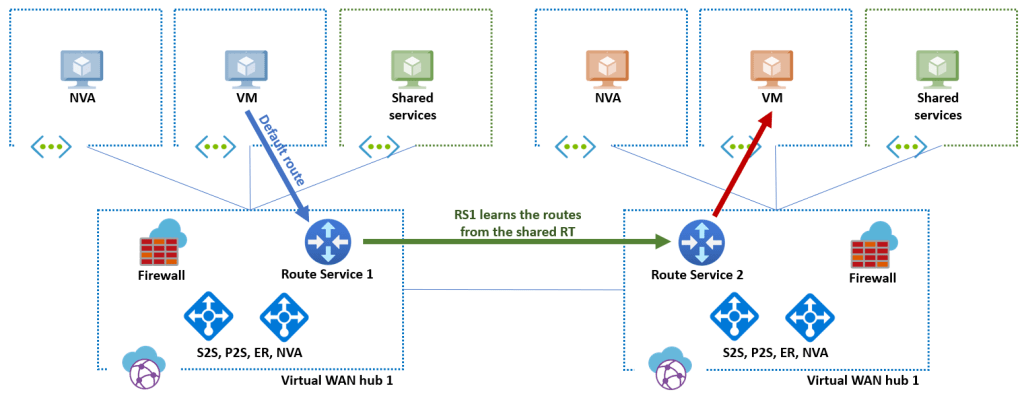
Why would they do that? Because the routing of those route service instances is actually not virtualized. In other words, while Virtual WAN supports multiple route tables or VRFs, those devices do not. By having a VNet in the shared VNet in hub 1, we are forcing the virtual routers in the hub to learn those routes, so this is what is happening (only the path from blue to red shown, the inverse path would be equivalent):
If you eliminate the shared services VNets from the hubs 1 and 2 (or just associate them a different route table such as “default”), you would see in the traceroute that the default route in the hub is now kicking in, and the routing instance in the hub is now sending traffic correctly to the NVA via the default route (hence, it is not learning any more the shared services routes). Red/blue traffic isolation is working again:
spoke11-vm (10.1.1.4)                                           2022-12-19T10:11:04+0000
Keys:  Help   Display mode   Restart statistics   Order of fields   quit
                                                Packets               Pings
 Host                                         Loss%   Snt   Last   Avg  Best  Wrst StDev
 1. 192.168.0.69                               0.0%     8    1.3   1.4   1.2   1.7   0.2
    192.168.0.68
 2. 10.1.2.4                                   0.0%     8    3.3   3.6   2.4   7.8   1.8
 3. ???
What about using Azure Firewall in the hub?
Testing with default routes to the Azure Firewall (as opposed as routes to an NVA in a spoke) I haven’t been able to break the isolation between red and blue. Although I am not sure if this is a bug or a feature. Looking forward to testing again when Virtual WAN routing intent will be released in General Availability!
Corollary
First of all, thanks for making it all the way down to here, congratulations! I have tried to prove in this post that you can use Virtual WAN to replicate your on-premises VRFs in Azure. The approach is not terribly scalable, since adding virtual hubs in each region for every VRF will originate additional costs. However, if you only have a couple of VRFs (like test and production), this might be a valid design and save you a couple of headaches.
If you have this setup in production or you have tested it and noticed something interesting that I didn’t describe here, please let me know!

Do you know when support for inter-region secure hub traffic will be available? it has hampered our adoption of secure hubs with several customers.
LikeLike
Hey Kyle, the indirect spoke model is today the best design to integrate Virtual WAN with a firewall (Azure Firewall or otherwise) across >1 region. To your question, the plan is to do it next year, for more accurate timelines you might want to check with your Microsoft account team 😉
LikeLike
This looks like another quite informative reading from your blog, thank you!
LikeLike
So glad you like it giuliohome!
LikeLiked by 1 person
[…] Chen tarjoilee listan linkkejä Azuren tietoturvan parhaisiin käytäntöihin. Azuren verkkovirtualisointi VRF:illä ei ole ihan helppoa. Virtual WAN:n custom routing on yksi vaihtoehto, jolla saa VRF-tyyppisen […]
LikeLike
Well, just a quick question – isn’t the proposed design not addressing one of the core VRF features , i.e. the use of overlapping address space in different VNETs peered with a vWAN hub ?
LikeLike
Good question Anton! Frankly I haven’t tested it. From a routing perapective it should work, but I don’t know if Virtual WAN has any preflight check that doesn’t allow to connect VNets with overlapping IPs to different hubs…
LikeLike
Hi Jose, great article, it was very informative. Do you see segmentation requirements as one of those opportunities for organizations to look at overlay technologies instead of trying to replicate on-premises technologies?
LikeLike
Thanks for reading VJ! Great question! Not sure if overlas are the answer to every question, but for certain requirements it does help indeed. Another area that we should be watching closely is identity-based networking (à la Zscaler), that might be the next-generation overlay.
LikeLike
Ah yes, or as the marketing team like to fondly refer to it as “Zero trust”.
LikeLiked by 1 person
Hi, That is great article. Unfortunately seems that we cannot play like this anymore.
Azure blocked possibility to – remove the “default” label from default route tables. you cannot remove or edit them. I was testing your ideas in my lab, I need such solution with Azure Firewalls at each Hub, however I have a problem with these default route tabels.
LikeLike
Yes, this is not compatible with the newest VWAN feature of Routing Intent. I will put a disclaimer at the top. Thanks for the comment!
LikeLike