
In Azure there are a couple of situations where you need to be careful with your User-Defined Routes, and after looking at some of them with other engineers we decided that a blog post around those might be interesting. So let’s go!
The most typical situation where you use User-Defined Routes (UDRs) in Azure is in combination with a network firewall, which can be either Azure Firewall or a Firewall from one of Microsoft’s partners. If using an Azure Firewall it is useful decomposing the Azure Firewall resource into its individual components. These are normally hidden from the normal user, but at times knowning about this can be the difference between solving a problem in 30 minutes or 1 week.
Essentially, an Azure Firewall is composed of two or more multiple instances with two load balancers in front of them: a public one (to get traffic from the public Internet), and an internal one (to get traffic from on-premises or the rest of the Azure Virtual Network environment). Something like this:

The following diagram illustrates then the design we are going to investigate. A hub and spoke model, with some common services in the hub, and an application served out of a virtual machine in the spoke. Route tables in the different subnets send traffic to the firewall, to make sure that every IP flow is inspected:

Flow: Application to Common Services
Let’s start with having a look of some of the flows in the diagram, for example the connectivity between the spokes and the Common Services in the hub. These Common Services might be anything such as Domain Controllers, DNS servers or file shares, and connections are typically initiated from the spokes. Lets walk this flow:
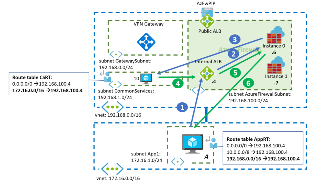
1. The spoke VM (172.16.1.4) sends a packet to the common services system (192.168.1.10). That packet will be intercepted by the UDR for 192.168.0.0/16, and it will be forwarded to the Azure Firewall’s insternal Load Balancer.
Source IP: 172.16.1.4
Destination IP: 192.168.1.10
2. The internal Azure Load Balancer in the firewall will pickup one of the firewall instances. In this particular example, it has picked up Instance 0.
3. The Azure Firewall instance will inspect the packet, and if it decides to forward it (instead of dropping it), it will forward it to the destination IP. Note that per default the Azure Firewall will not Source NAT private IP addresses (RFC 1918), so no change in the packet addresses:
Source IP: 172.16.1.4
Destination IP: 192.168.1.10
4. The common services VM answers, and Azure sends the packet to the Azure Firewall’s internal load balancer as per the User-Defined Route configured in the CSRT (Common Services Route Table) for 172.16.0.0/16:
Source IP: 192.168.1.10
Destination IP: 172.16.1.4
5. Now the load balancer needs to choose the firewall instance to process the packet. Any given Azure Load Balancer will choose the same backend instance for the same packet attributes (even if they are reversed). In this case, the source and destination IP addresses are the same than in the step 2 but reversed (the source is now the destination, and the destination is now the source), so the Azure Load Balancer will pick Instance 0 again .
6. The Azure Firewall Instance 0 already knows about that TCP flow, since it saw the initial packet, and it will allow it and forward it to its destination in the spoke.
Source IP: 192.168.1.10
Destination IP: 172.16.1.4
So everything good, right? There is one problem with this design though, that the following flow will explain.
Flow: Internet to Application
Now we will look at an Internet user trying to reach the application in the spoke through the Azure Firewall’s public IP:

1. In this case, the traffic is initiated from the public Internet. The application client will reach the public IP address of the Azure Firewall (AzFWPIP in the diagram). That public IP address is actually configured in the public Azure Load Balancer
Source IP: ClientPIP
Destination IP: AzFWPIP
2. The public Load Balancer will pick up one of the Azure Fireall instances, in this particular example the Instance 1 (I believe that the public ALB is configured with Floating IP aka Direct Server Return, but this is not relevant for this blog):
Source IP: ClientPIP
Destination IP: AzFWPIP
3. The Azure Firewall instance will destination-NAT the traffic (assuming here a DNAT rule is configured in the Azure Firewall). Additionally it will source-NAT the packet to make sure that return traffic comes to the same instance. Finally, it will forward it to the application in the spoke
Source IP: 192.168.100.7
Destination IP: 172.16.1.4
4. And here we finally have the problem: when the virtual machine in the spoke answers, the return traffic will go to 192.168.100.7. This destination is covered by the UDR 192.168.0.0/16, so Azure will send it to the Azure Firewall’s internal load balancer
Source IP: 172.16.1.4
Destination IP: 192.168.100.7
5. This internal load balancer is different that the public load balancer that saw the inbound packet from the client, so it might as well pick a different firewall instance than the one used for the inbound flow. If we assume the worst case, the internal load balancer will pick now the Azure Firewall Instance 0. This Azure Firewall instance has not seen the inbound packet, so it will consequently dropped this packet as an answer to a question that has never been asked (or a SYN ACK packet for which a SYN packet has never been seen). Oh no.
How can we avoid this? The problem here is that we put the UDR to the whole hub vnet prefix 192.168.0.0/16 in the AppRT route table (the route marked in red in the above diagram), and this includes the IP addresses of the individual firewall instances. However, when a packet comes sourced from one of the firewall instances we want to go straight to it, not through the Azure Load Balancer. There are two ways of doing this:
- You could add more specific routes to the route table as exceptions. You might be tempted to use the next-hop type “VnetLocal” (also known as “Virtual Network” in the portal), but that is only valid for the local vnet, and not for a peered one. Instead, here you would have to add each individual IP address for the firewall instances:
192.168.100.6/32 -> 192.168.100.6 (next-hop type “Virtual Appliance”)
192.168.100.7/32 -> 192.168.100.7 (next-hop type “Virtual Appliance”) - The previous approach might be acceptable if you know in advance the private IP addresses of your firewall, but in some cases (like with the Azure Firewall) you will not know them. You can of course guess, but an alternative is configuring a smaller UDR that does not cover the AzureFirewallSubnet. Instead of sending the whole hub IP space to the Azure Firewall, you actually only need to specify the subnets where your common services are located, as the following diagram suggests:

As you can see here, when the application in the spoke answers to the firewall, the return packets will not be intercepted by any route, and will flow normally through the VNet peering back to the instance that originated them.
The flow between the spoke and the common services subnet in the hub should still work, as the UDR for 192.168.1.0/24 covers those systems. If there were further subnets in the hub that need to be exposed to the spokes through the firewall, you would have to add subsequent routes to the route table in the spoke.
Flow: On-premises to Application
Let’s change gears a bit. Let’s assume that there is an on-premises site connected via a site-to-site VPN tunnel to our virtual network. In order to support traffic from on-premises to our application a route table is needed in the GatewaySubnet where the Azure VPN Gateway is located:

We will not do the full packet walk here, but let’s highlight a couple of points:
- When traffic leaves the VPN Gateway (packet 2), the UDR in the gateway subnet for 172.16.0.0/16 will send it to the Azure Firewall. The other UDR in the gateway subnet for 192.168.0.0/16 has been included to inspect traffic from on-premises to the Common Services subnet.
- The Azure Firewall will not source-NAT traffic, so the inbound and outbound packets will traverse the same internal Load Balancer, and will have identically source and destination addresses and ports (but reversed). Hence the same Azure Firewall instance will be picked for packets 3 and 6 (instance 1 in this example).
So far so good! Imagine however in this case that the customer decides to deploy an ExpressRoute gateway into the design. Once the ExpressRoute Gateway has been deployed (even before connecting it to an ExpressRoute circuit), flows to on-premises will break. Why? What happened?
There is a longer explanation involved, but take my TL;DR here: if you have both types of gateways in an Azure Virtual Network, they need to speak internal BGP to each other. However, the route for 192.168.0.0/16 in the GatewaySubnet was sending traffic between the two gateways to the Azure Firewall, which will probably drop it:

When that happens, the ExpressRoute gateway will not learn the prefixes from the VPN gateway, and will not inject anything into the Vnet. As a consequence, the Azure Firewall will not know how to go back to the on-premises network.
The fix for this is similar as for the asymmetric flow from earlier:
- You can exclude the GatewaySubnet’s prefix from the existing UDR with a more specific route pointing to VnetLocal (this time you can use it because the destination is in the same Vnet)
- Or you can make the initial route to 192.168.0.0/16 more specific so that it does not contain the GatewaySubnet. For example, reducing it to just the CommonServices subnet (192.168.1.0/24)
I prefer the second method, as I reflect in this diagram:

And that’s it! In this blog I went over some intricacies of UDRs in Azure that can cause problems with SNAT and with the coexistence of VPN and ExpressRoute gateways. I hope it helped!

Hello, so for ExpressRoute Gateway those records are fine?
192.168.0.0 -> AzFW
172.16.0.0/12 (!) -> AzFW
But if we add VPN Gateway we should add 192.168.0.0 -> Virtual network?
LikeLike
Hello! Not sure I understand the question. As the blog explains in the last section, if there is a route for the Hub VNet prefix (192.168.0.0/16 in the example), that will break multiple things, so the recommended behavior is having UDRs only for the workload subnets in the hub, or alternatively if you have too many workload subnets, to add routes for the non-workload subnets (GatewaySubnet, AzureFirewallSubnet, Application Gateway, APIM, etc) with next hop type VirtualNetwork. Either option will work.
Hth!
LikeLike
Additionally, there is no difference between ER and VPN VNGs from an UDR perspective, since both live in the same subnet.
LikeLike
Thanks for swift reply, appreciate that.
Let me split your reply and refer to it
[…]”if there is a rout for the Hub VNet prefix (192.168.0.0/16 in the example), that will break multiple things”[…]
If we want to filter traffic from Onpremise we need to setup Route Table for GatewaySubnet, right?
Then we need to setup UDR like this to filter incoming traffic to Azure and avoid Azure – onprem connection disruption:
192.168.0.0 -> AzFW
172.16.0.0/12 (!) -> AzFW
192.168.0.0 -> Virtual network (required when adding another gateway to preserve ibgp routing between gateways
—
I don’t understand the second part, what is the purpose of setting up UDR with next hop type VirtualNetwork to for ApplicationGateway / APIM subnet in a Hub?
Maybe because I do not prefere setting up those services in a Hub.
[…]”the recommended behavior is having UDRs only for the workload subnets in the hub, or alternatively if you have too many workload subnets, to add routes for the non-workload subnets (GatewaySubnet, AzureFirewallSubnet, Application Gateway, APIM, etc) with next hop type VirtualNetwork.”
LikeLike
OK, let me try to clarify:
1. If you want to send onprem->spoke traffic from the VNG to the firewall, you need a route in the GatewaySubnet for the spoke prefixes (172.16.0.0/16 in the example above), with next hop the FW. If you don’t have services in the hub, you can stop reading.
2. If you have services in the hub, and you need to send traffic from onprem to those services through the FW, you have two alternatives:
2a: You create a route for the services subnets (192.168.1.0/24 in this example), with next hop the Firewall.
2b: You create a route in the GatewaySubnet for the whole hub (192.168.0.0/16) with next hop the Firewall, and then you add two additional routes for the GatewaySubnet (192.168.0.0/24 in the example) and for the AzureFirewallSubnet (192.168.100.0/24), both with next hop type VirtualNetwork. Otherwise you create asymmetric traffic as explained in the article.
Does that make sense?
LikeLike
Many thanks for that! 🙂
LikeLike
Very neatly explained all the intricacies, these are real world issues and don’t understand why there are no documentation from Microsoft publicly available. Well done Jose.
LikeLike
Happy it helps Thanga, thanks for the kind words!
LikeLike
Hello! Perhaps it’s just me but I’m not quite following your solution to the “Flow: Internet to Application” scenario.
You say “As you can see here, when the application in the spoke answers to the firewall, the return packets will not be intercepted by any route, and will flow normally through the VNet peering back to the instance that originated them”, but don’t the return packets still go via the 0.0.0.0/0 route and hit 192.168.100.4 which is the internal ALB which means we have the same asymmetric routing problem still?
LikeLike
Hey thanks for reading! I am sorry it is not clear. The return packets, which are SNATted by the AzFW, will hit the VNet peering route (192.168.0.0/16), not the 0.0.0.0/0.
LikeLiked by 1 person
Hm ok but how does that explain why the packet will still go directly to the (right) firewall? I can see the VNet peer route in the RT but there is no next hop. Is it implied?
LikeLike
Yepp, that is just how VNet peering works. If VM1 in VNet1 wants to talk to VM2 in Vnet2, it is enough with peering both VNets, so that the new route will have a next hop type of “VNet Peering”
LikeLiked by 1 person
Hi Jose,
I have a similar hub n spoke deployment with Azure Firewall alone in the hub vnet. Spoke vnets host application workloads and have UDRs to the firewall private up as next hop.
I’ve being troubleshooting issues with connectivity from application to database and noticed deny traffic (UDP only) logged in the Azure firewall logs during the time of the issue. The strange thing is that these denies appears to be the response and not the request. This leads me to believe it’s some sort of an asymmetric issue on the Azure firewall. Note: There are no logs for TCP denies which tells me that the syn-ack packets were probably dropped and therefore no log produced.
Thoughts on what can be going wrong here?
LikeLike
Hey Frank,
– Where are the databases? In the same VNet?
– On which UDP port are the dropped packets? If it is 1434, it could be relates to https://www.sqlnethub.com/blog/sql-server-browser-service-udp-port-1434/
LikeLike
App and db are in spoke vnets separated from each other by the hub firewall. Dropped UDP traffic is not related to any SQL ports; more like DNS, NTP. It seems like dropped TCP packets are not being logged.
LikeLike
Mmmh that sounds weird. Support ticket?
LikeLike
Yup. Will post back here how it goes
LikeLike
@Frank did you solve the issue in the end?
LikeLike
Yes, as it turns out the Azure Firewall was dropping packets due to congestion and it couldn’t scale out to handle the load. It was manually scaled up by the Azure support team.
LikeLike
Hi Frank, what FW SKU did you scale-up from, I assume Premium, else you would have just upgraded to Premium?
LikeLike
Yes, premium sku
LikeLike
[…] https://blog.cloudtrooper.net/2020/11/28/dont-let-your-azure-routes-bite-you/ […]
LikeLike
[…] route for the actual hub VNet? Some years ago I wrote this article about how to do this properly: Don’t let your Azure Routes bite you. The corollary is that you shouldn’t create a route in your GatewaySubnet for the whole […]
LikeLike
Jose, this is great content. Thanks for sharing. I am very surprised that MS doesn’t have documentation around some of these details as it seems that traffic flows might be affected in unanticipated ways.
You write that the Azure FW is a construct composed of multiple LBs + multiple instances. Is the FW IP exposed to the user in the console some kind of VIP that isn’t associated with either LB?
Jeff L.
LikeLike
I am happy this is useful Jeff! Absolutely, the IP addresses you see in the portal associated to the Azure Firewall are actually the IP addresses of the load balancers (public and internal) running under the covers.
LikeLike
Always amazing content … 5 years old and still shiny gem!
Couple of questions on last scenario …
1) I would expect VMs in the same subnet (ER and VPN gateways in this case) talk freely and the UDR being applied only when traffic leaves the subnet… am I wrong?
2) Would routes exchange between ER and VPN gateways work with the whole hub CIDR (192.168.0.0/16) and just allow BGP traffic in the Azure Firewall with source and destination the GatewaySubnet CIDR?
Thanks for rocking so much!
LikeLike
Hey Jay so glad this is useful!
1) is wrong: UDRs are enforced at the NIC for all traffic, regardless if it is going to a destination in the same subnet or not.
2) I am not sure I understand the question…
LikeLike
Thanks for clarification on 1, that’s something I did not found documented… now it is 🙂
Regarding 2, let me clarify a bit ..
You stated that “if you have both types of gateways in an Azure Virtual Network, they need to speak internal BGP to each other. However, the route for 192.168.0.0/16 in the GatewaySubnet was sending traffic between the two gateways to the Azure Firewall, which will probably drop it“
So question is … if the firewall allows that BGP traffic between gateways across, will I still need to swap the route for 192.168.0.0/16 in the GatewaySubnet with routes to exclude the GatewaySubnet, or allowing the traffic in the firewall fixes the problem without having to add routes for every new “CommonServices” subnets that are added over time.
Thanks again!
LikeLike
Ah gotcha! Probably yes, if you allow in your firewall all communication inside of the GatewaySubnet it would likely work. I wouldn’t recommend that setup though, in my opinion it is too fragile.
LikeLike